Question 1
Question: To an ac power supply of 220 V at 50 Hz, a resistor of $20 \Omega$, a capacitor of reactance $25 \Omega$ and an inductor of reactance $45 \Omega$ are connected in series. The corresponding current in the circuit and the phase angle between the current and the voltage is, respectively.
Options:
A. 15.6 A and $30^\circ$
B. 15.6 A and $45^\circ$
C. 7.8 A and $30^\circ$
D. 7.8 A and $45^\circ$
Correct Answer: D
Year: NEET 2025
Solution (as Given in the Source): Current $I = \frac{V}{\sqrt{(X_L - X_C)^2 + R^2}} = \frac{220}{\sqrt{(45-25)^2 + 20^2}} = \frac{220}{\sqrt{20^2 + 20^2}} = \frac{11}{\sqrt{2}} \approx 7.8 \text{ A}$. Phase angle $\tan \phi = \frac{X_L - X_C}{R} = \frac{45 - 25}{20} = 1 \Rightarrow \phi = 45^\circ$.
Step Solution:
1. Identify parameters: $V = 220 \text{ V}$, $R = 20 \Omega$, $X_L = 45 \Omega$, and $X_C = 25 \Omega$.
2. Calculate Impedance ($Z$): $Z = \sqrt{R^2 + (X_L - X_C)^2} = \sqrt{20^2 + (45-25)^2} = \sqrt{800} = 20\sqrt{2} \Omega$.
3. Calculate RMS Current ($I$): $I = \frac{V}{Z} = \frac{220}{20\sqrt{2}} = \frac{11}{\sqrt{2}} \approx 7.779 \text{ A}$ (rounded to 7.8 A).
4. Calculate Tangent of Phase Angle: $\tan \phi = \frac{X_L - X_C}{R} = \frac{20}{20} = 1$.
5. Determine Phase Angle ($\phi$): Since $\tan \phi = 1$, $\phi = \tan^{-1}(1) = 45^\circ$.
Difficulty Level: Medium
Concept Name: Series LCR Circuit Impedance and Phase.
Short cut solution: Since $R = (X_L - X_C) = 20$, the circuit forms an isosceles right triangle for impedance, meaning $\phi$ must be $45^\circ$ and $Z = R\sqrt{2} = 20\sqrt{2}$.
Question 4
Question: In the circuit shown below, the inductance L is connected to an ac source. The current flowing in the circuit is $I = I_0 \sin \omega t$. The voltage drop $(V_L)$ across L is.
Options:
A. $\omega L I_0 \sin \omega t$
B. $\frac{I_0}{\omega L} \sin \omega t$
C. $\frac{I_0}{\omega L} \cos \omega t$
D. $\omega L I_0 \cos \omega t$
Correct Answer: D
Year: NEET 2024 Re
Solution (as Given in the Source): $V_L$ leads current $I$ by $\frac{\pi}{2}$. $\therefore V_L = V_0 \sin(\omega t + \frac{\pi}{2})$. Given $V_0 = I_0 X_L$, then $V_L = I_0 X_L \cos(\omega t) = I_0 \omega L \cos(\omega t)$.
Step Solution:
1. Start with Current Equation: $I = I_0 \sin \omega t$.
2. Apply Phase Relationship: In a pure inductive circuit, voltage leads current by a phase of $\frac{\pi}{2}$.
3. Write Voltage Equation: $V_L = V_0 \sin(\omega t + \frac{\pi}{2})$.
4. Substitute Peak Voltage ($V_0$): $V_0 = I_0 X_L = I_0 (\omega L)$.
5. Simplify using Trig Identity: $\sin(\omega t + \frac{\pi}{2}) = \cos \omega t$, yielding $V_L = \omega L I_0 \cos \omega t$.
Difficulty Level: Easy
Concept Name: Phase Relationship in a Pure Inductive Circuit.
Short cut solution: In a pure inductor, voltage leads current by $90^\circ$. If current is $\sin \omega t$, voltage must be $\cos \omega t$ with an amplitude of $I_0 \times X_L$ (where $X_L = \omega L$).
Question 6
Question: The amplitude of the charge oscillating in a circuit decreases exponentially as $Q = Q_0 e^{-Rt/2L}$, where $Q_0$ is the charge at $t = 0 \text{ s}$. The time at which charge amplitude decreases to $0.50 Q_0$ is nearly: [Given that $R = 1.5 \Omega, L = 12 \text{ mH}, \ln(2) = 0.693$].
Options:
A. 19.01 ms
B. 11.09 ms
C. 19.01 s
D. 11.09 s
Correct Answer: B
Year: NEET 2024 Re
Solution (as Given in the Source): $0.5 Q_0 = Q_0 e^{-Rt/2L} \Rightarrow \frac{1}{2} = e^{-Rt/2L}$. Taking log on both sides: $\ln 2 = \frac{Rt}{2L}$. $t = \frac{2 L \ln 2}{R} = \frac{2 \times 12 \times 10^{-3} \times 0.693}{1.5} = 11.09 \text{ ms}$.
Step Solution:
1. Set up Decay Equation: Substitute $Q = 0.5 Q_0$ into $Q = Q_0 e^{-Rt/2L}$ to get $0.5 = e^{-Rt/2L}$.
2. Apply Natural Logarithm: $\ln(0.5) = -Rt/2L \Rightarrow -\ln(2) = -Rt/2L \Rightarrow \ln(2) = \frac{Rt}{2L}$.
3. Isolate Time ($t$): $t = \frac{2 L \ln 2}{R}$.
4. Substitute Constants: $t = \frac{2 \times (12 \times 10^{-3}) \times 0.693}{1.5}$.
5. Calculate Final Value: $t = \frac{0.016632}{1.5} = 0.011088 \text{ s} \approx 11.09 \text{ ms}$.
Difficulty Level: Hard
Concept Name: Damped Oscillations (Exponential Decay).
Short cut solution: Use $t = \tau \ln 2$, where $\tau$ (time constant) is $2L/R$. $\tau = 24 \text{ mH} / 1.5 \Omega = 16 \text{ ms}$. Then $16 \times 0.693 \approx 11.1 \text{ ms}$.
Question 8
Question: A 10µF capacitor is connected to a 210V, 50Hz source as shown in figure. The peak current in the circuit is nearly $(\pi = 3.14)$ :
Options:
A. 0.58A
B. 0.93A
C. 1.20A
D. 0.35A
Correct Answer: B
Year: NEET 2024
Solution (as Given in the Source):
Capacitive Reactance $X_C = \frac{1}{\omega C} = \frac{1}{2 \pi f C} = \frac{1}{2 \times 3.14 \times 50 \times 10 \times 10^{-6}} = \frac{1000}{3.14}$.
$V_{rms} = 210 \text{ V}$.
$i_{rms} = \frac{V_{rms}}{X_C} = \frac{210}{X_C}$.
Peak current $= \sqrt{2} i_{rms} = \sqrt{2} \times \frac{210}{1000} \times 3.14 = 0.932 \approx 0.93 \text{ A}$.
Step Solution:
1. Calculate $X_C$: $X_C = \frac{1}{2\pi f C} = \frac{1}{2 \times 3.14 \times 50 \times 10 \times 10^{-6}} = \frac{10^6}{3140} = \frac{1000}{3.14} \Omega$.
2. Identify $V_{rms}$: Given $V_{rms} = 210 \text{ V}$.
3. Calculate RMS current ($i_{rms}$): $i_{rms} = \frac{V_{rms}}{X_C} = \frac{210 \times 3.14}{1000} = 0.6594 \text{ A}$.
4. Relate RMS to Peak current ($i_0$): $i_0 = \sqrt{2} \times i_{rms}$.
5. Final Calculation: $i_0 = 1.414 \times 0.6594 \approx 0.93 \text{ A}$.
Difficulty Level: Medium
Concept Name: Capacitive Reactance and RMS to Peak Current Conversion.
Short cut solution: $i_0 = \sqrt{2} V_{rms} (2\pi f C) = 1.414 \times 210 \times 314 \times 10^{-5} \approx 0.93 \text{ A}$.
Question 11
Question: In a series LCR circuit, the inductance L is 10mH, capacitance C is 1µF and resistance R is 100Ω. The frequency at which resonance occurs is
Options:
A. 15.9kHz
B. 1.59rad∕ s
C. 1.59kHz
D. 15.9rad∕ s
Correct Answer: C
Year: NEET 2023
Solution (as Given in the Source):
$f = \frac{1}{2 \times \pi \times \sqrt{10 \times 10^{-3} \times 1 \times 10^{-6}}} = \frac{10^4}{2 \pi} = 1.591 \times 10^3 = 1.591 \text{ kHz}$.
Step Solution:
1. Identify Resonance formula: $f = \frac{1}{2\pi\sqrt{LC}}$.
2. Substitute values: $L = 10 \times 10^{-3} \text{ H}$ and $C = 1 \times 10^{-6} \text{ F}$.
3. Calculate product: $LC = 10 \times 10^{-9} = 10^{-8}$.
4. Find square root: $\sqrt{10^{-8}} = 10^{-4}$.
5. Final Calculation: $f = \frac{1}{2\pi \times 10^{-4}} = \frac{10^4}{2\pi} \approx 1591.5 \text{ Hz} \approx 1.59 \text{ kHz}$.
Difficulty Level: Easy
Concept Name: Resonant Frequency of a Series LCR Circuit.
Short cut solution: $f = \frac{1}{2\pi\sqrt{LC}}$. Since $LC = 10^{-8}$, $f = \frac{10^4}{2\pi} \approx 1.59 \text{ kHz}$.
Question 13
Question: The net impedance of circuit (as shown in figure) will be
Options:
A. 15Ω
B. 5√5Ω
C. 25Ω
D. 10√2Ω
Correct Answer: B
Year: NEET 2023 mpr
Solution (as Given in the Source):
$L = \frac{50}{\pi} \text{ mH} \Rightarrow X_L = 2 \pi \times 50 \times \frac{50}{\pi} \times 10^{-3} = 5 \Omega$.
$C = \frac{10^3}{\pi} \times 10^{-6} \Rightarrow X_C = \frac{1 \times \pi}{2 \pi \times 50 \times 10^3 \times 10^{-6}} = \frac{10^3}{100} = 10 \Omega$.
$Z = \sqrt{(X_C - X_L)^2 + R^2} = \sqrt{(10 - 5)^2 + 10^2} = \sqrt{125} = 5\sqrt{5} \Omega$.
Step Solution:
1. Calculate $X_L$: $X_L = \omega L = (100\pi) \times (\frac{50}{\pi} \times 10^{-3}) = 5 \Omega$.
2. Calculate $X_C$: $X_C = \frac{1}{\omega C} = \frac{1}{(100\pi) \times (\frac{10^3}{\pi} \times 10^{-6})} = 10 \Omega$.
3. Determine Resistance: From the solution steps, $R = 10 \Omega$.
4. Find Reactance Difference: $|X_C - X_L| = |10 - 5| = 5 \Omega$.
5. Apply Impedance formula: $Z = \sqrt{R^2 + (X_C - X_L)^2} = \sqrt{10^2 + 5^2} = \sqrt{125} = 5\sqrt{5} \Omega$.
Difficulty Level: Medium
Concept Name: Impedance in a Series LCR Circuit.
Short cut solution: Find $X_L=5$ and $X_C=10$. The vector sum of $R=10$ and $X_{net}=5$ is $\sqrt{10^2+5^2} = 5\sqrt{5} \Omega$.
Question 14
Question: An ac source is connected in the given circuit. The value of $\phi$ will be: $V = 220 \sin(100\pi t + \phi)$ volt.
Options:
A. $60^\circ$]
B. $90^\circ$
C. $30^\circ$
D. $45^\circ$
Correct Answer: D
Year: NEET 2023 mpr
Solution (as Given in the Source):
$\tan \phi = \frac{X_L}{R}$
$X_L = \omega l = 100\pi \times \frac{1}{\pi} = 100 \Omega$
$R = 100 \Omega$
$\tan \phi = \frac{100}{100} = 1 \Rightarrow \phi = 45^\circ$
Step Solution:
1. Identify angular frequency ($\omega$): From the voltage equation $V = 220 \sin(100\pi t + \phi)$, $\omega = 100\pi$.
2. Determine Inductive Reactance ($X_L$): Use the formula $X_L = \omega L$. Given $L = 1/\pi$ H, $X_L = 100\pi \times (1/\pi) = 100 \Omega$.
3. Identify Resistance ($R$): The circuit resistance is given as $R = 100 \Omega$.
4. Apply Phase Angle Formula: For an RL circuit, $\tan \phi = X_L / R$.
5. Calculate $\phi$: $\tan \phi = 100 / 100 = 1$. Therefore, $\phi = \tan^{-1}(1) = 45^\circ$.
Difficulty Level: Easy
Concept Name: Phase Angle in an RL Circuit.
Short cut solution: Since $R = X_L$, the phase angle must be $45^\circ$ because $\tan(45^\circ) = 1$.
Question 15
Question: If $Z_1$ and $Z_2$ are the impedances of the given circuits (a) and (b) as shown in figures, then choose the correct option.
Options:
A. $Z_1 < Z_2$
B. $Z_1 = Z_2$
C. $Z_1 + Z_2 = 20 \Omega$
D. $Z_1 > Z_2$
Correct Answer: A
Year: NEET 2023 mpr (Contextual)
Solution (as Given in the Source):
$Z_1 = \sqrt{X_L^2 + R^2}$ where $X_L = 0$ (D.C. circuit). $Z_1 = 10 \Omega$.
$Z_2 = \sqrt{X_C^2 + R^2}$ where $X_C = \frac{1}{2 \pi \times 50 \times \frac{10^3}{\pi} \times 10^{-6}} = 10 \Omega$.
$Z_2 = \sqrt{10^2 + 10^2} = 10\sqrt{2}$.
$Z_1 < Z_2$.
Step Solution:
1. Analyze Circuit (a) (DC): In a DC circuit, frequency $f = 0$, so an inductor acts as a short circuit ($X_L = 0$).
2. Calculate $Z_1$: Since $X_L = 0$, $Z_1 = R = 10 \Omega$.
3. Analyze Circuit (b) (AC): Calculate capacitive reactance using $X_C = 1 / (2\pi f C)$.
4. Substitute values for $X_C$: $X_C = 1 / (2\pi \times 50 \times \frac{10^3}{\pi} \times 10^{-6}) = 10 \Omega$.
5. Calculate $Z_2$ and Compare: $Z_2 = \sqrt{10^2 + 10^2} = 10\sqrt{2} \approx 14.14 \Omega$. Thus, $Z_1 < Z_2$.
Difficulty Level: Medium
Concept Name: AC vs DC Impedance.
Short cut solution: Inductors have zero reactance in DC ($Z=10$), while capacitors have finite reactance in AC, increasing the total impedance ($Z > 10$).
Question 16
Question: The maximum power is dissipated for an ac in a/an:
Options:
A. resistive circuit
B. LC circuit
C. inductive circuit
D. capacitive circuit
Correct Answer: A
Year: NEET 2023 mpr
Solution (as Given in the Source): Power dissipated is maximum of purely resistive circuit.
Step Solution:
1. Recall Average Power Formula: $P_{avg} = V_{rms} I_{rms} \cos \phi$.
2. Evaluate Inductive/Capacitive Circuits: For pure $L$ or $C$, the phase difference $\phi = 90^\circ$.
3. Calculate Power Factor: $\cos 90^\circ = 0$, meaning zero power is dissipated in ideal $L$ or $C$ components.
4. Evaluate Resistive Circuit: For a pure resistor, the phase difference $\phi = 0^\circ$.
5. Conclude: Since $\cos 0^\circ = 1$ (the maximum possible power factor), power dissipation is maximum in a resistive circuit.
The difficulty level: Easy
The Concept Name: Power in AC Circuits.
Short cut solution: Only resistors dissipate real power in AC circuits; pure inductors and capacitors are "wattless" because their phase shift is $90^\circ$.
Question 18
Question: For very high frequencies, the effective impedance of the circuit (shown in the figure) will be :-
Options:
A. 4$\Omega$
B. 6$\Omega$
C. 1$\Omega$
D. 3$\Omega$
Correct Answer: D
Year: NEET 2023 mpr
Solution (as Given in the Source): as frequency is very high, $X_C \approx 0$, $X_L \rightarrow \infty$.
Effective circuit will be Effective impedance of circuit will be $Z = 3 \Omega$.
Step Solution:
1. Analyze Reactance behavior: At very high frequencies ($f \rightarrow \infty$), inductive reactance $X_L = 2\pi f L$ becomes infinitely large ($\infty$), and capacitive reactance $X_C = \frac{1}{2\pi f C}$ becomes zero (0).
2. Determine Branch States: The branch with the inductor acts as an open circuit (infinite resistance), and the branch with the capacitor acts as a short circuit (zero resistance).
3. Simplify Circuit: Remove the open branches containing inductors and treat the capacitor branch as a plain wire.
4. Identify Resistance: The simplified circuit leaves only the resistive component mentioned in the source.
5. Calculate Impedance: The total effective impedance is the remaining resistance, $Z = 3 \Omega$.
Difficulty Level: Medium
Concept Name: High-Frequency Response of Reactive Components.
Short cut solution: At high frequencies, "L" is an open switch and "C" is a closed wire. Only the $3\Omega$ resistance remains in the path.
Question 20
Question: Given below are two statements. Statement I: In an ac circuit, the current through a capacitor leads the voltage across it. Statement II: In a.c circuits containing pure capacitance only, the phase difference between the current and the voltage is $\pi$. In the light of the above statements, choose the most appropriate answer from the options given below.
Options:
A. Statement I is incorrect but Statement II is correct
B. Both Statement and Statement II are correct
C. Both Statement I and Statement II are incorrect
D. Statement I is correct but Statement II is incorrect
Correct Answer: D
Year: NEET Re-2022
Solution (as Given in the Source): In AC circuit current through the capacitor leads the potential difference across it by a phase $\pi / 2$.
Step Solution:
1. Evaluate Statement I: According to the theory of capacitive circuits, current leads the potential difference. Statement I is correct.
2. Recall Phase Relationship: In a purely capacitive circuit, the current leads the voltage by exactly $90^\circ$ or $\pi/2$ radians.
3. Evaluate Statement II: The statement claims the phase difference is $\pi$ ($180^\circ$).
4. Comparison: Since the actual phase difference is $\pi/2$ and not $\pi$, Statement II is incorrect.
5. Conclusion: Statement I is correct and Statement II is incorrect.
Difficulty Level: Easy
Concept Name: Phase Relationships in Capacitive AC Circuits.
Short cut solution: Remember the mnemonic CIVIL: In a Capacitor, I (current) leads V (voltage). The lead is always $90^\circ$ ($\pi/2$), making Statement II's claim of $\pi$ false.
Question 21
Question: An inductor of inductance 2 mH is connected to a 220V, 50 Hz a.c. source. Let the inductive reactance in the circuit is $X_1$. If a 220V dc source replaces the ac source in the circuit, then the inductive reactance in the circuit is $X_2$. $X_1$ and $X_2$ respectively are
Options:
A. 0.628$\Omega$, infinity
B. 6.28$\Omega$, zero
C. 6.28$\Omega$, infinity
D. 0.628$\Omega$, zero
Correct Answer: D
Year: NEET Re-2022
Solution (as Given in the Source): Given $L = 2 mH, f = 50 Hz$. When A.C. source is applied $X_1 = \omega L = 2 \pi f L = 2 \pi \times 50 \times 2 \times 10^{-3} = .628 \Omega$. When D.C. source is applied $X_2 = \omega L = 2 \pi f L$ (since $f = 0$ for DC), $X_2 = 0$.
Step Solution:
1. Identify A.C. Data: $L = 2 \times 10^{-3}$ H and $f = 50$ Hz.
2. Calculate $X_1$: $X_1 = 2 \times \pi \times 50 \times 2 \times 10^{-3}$.
3. Solve for $X_1$: $X_1 = 200\pi \times 10^{-3} \approx 0.628 \Omega$.
4. Analyze D.C. Case: In a D.C. circuit, the frequency $f$ is zero.
5. Calculate $X_2$: $X_2 = 2 \pi (0) L = 0 \Omega$.
Difficulty Level: Easy
Concept Name: Inductive Reactance ($X_L = \omega L$).
Short cut solution: Inductors offer zero reactance to DC. Therefore, $X_2$ must be 0. Looking at the options, only D has $X_2 = 0$.
Question 22
Question: A standard filament lamp consumes 100W when connected to 200V ac mains supply. The peak current through the bulb will be:
Options:
A. 2A
B. 0.707A
C. 1A
D. 1.414
Correct Answer: B
Year: NEET Re-2022
Solution (as Given in the Source):
Given, $P = 100 \text{ W}, V_{\text{rms}} = 200 \text{ V}$
$i_{\text{rms}} = \frac{P}{V_{\text{rms}}} = \frac{100}{200} = \frac{1}{2}$
$i_0 = i_{\text{rms}} \times \sqrt{2} = \frac{1}{2} \times \sqrt{2} = \frac{1}{\sqrt{2}}$
$i_0 = 0.707 \text{ A}$
Step Solution:
1. Identify Given Values: Power $P = 100 \text{ W}$ and RMS Voltage $V_{\text{rms}} = 200 \text{ V}$.
2. Calculate RMS Current ($i_{\text{rms}}$): $i_{\text{rms}} = \frac{P}{V_{\text{rms}}} = \frac{100}{200} = 0.5 \text{ A}$.
3. State Peak Current Formula: $i_0 = i_{\text{rms}} \times \sqrt{2}$.
4. Perform Calculation: $i_0 = 0.5 \times 1.414 = 0.707 \text{ A}$.
The difficulty level: Easy
The Concept Name: RMS and Peak Current Relationship.
Short cut solution: Peak current is $1.414$ times the RMS current. $i_0 = 1.414 \times (100/200) = 0.707 \text{ A}$.
Question 23
Question: The peak voltage of the ac source is equal to
Options:
A. The value of voltage supplied to the circuit
B. The rms value of the ac source
C. $\sqrt{2}$ times the rms value of the ac source
D. $1 / \sqrt{2}$ times the rms value of the ac source
Correct Answer: C
Year: NEET-2022
Solution (as Given in the Source):
We know, $E_{\text{rms}} = \frac{E_0}{\sqrt{2}} \Rightarrow E_0 = \sqrt{2} E_{\text{rms}}$
Step Solution:
1. Define Terms: $E_0$ is the peak voltage and $E_{\text{rms}}$ is the root mean square voltage.
2. State the Relation: For a sinusoidal AC source, $E_{\text{rms}} = \frac{E_0}{\sqrt{2}}$.
3. Rearrange for Peak Voltage: Multiply both sides by $\sqrt{2}$ to get $E_0 = \sqrt{2} \times E_{\text{rms}}$.
The difficulty level: Easy
The Concept Name: RMS and Peak Voltage Relationship.
Short cut solution: In AC, the peak value is always $\sqrt{2}$ ($\approx 1.414$) times the RMS value.
Question 25
Question: A series LCR circuit with inductance 10H, capacitance 10µF, resistance 50Ω is connected to an ac source of voltage, $V = 200 \sin(100t) \text{ volt}$. If the resonant frequency of the LCR circuit is $v_0$ and the frequency of the ac source is $v$, then
Options:
A. $v_0 = v = 50 \text{ Hz}$
B. $v_0 = v = \frac{50}{\pi} \text{ Hz}$
C. $v_0 = \frac{50}{\pi} \text{ Hz}, v = 50 \text{ Hz}$
D. $v = 100 \text{ Hz}; v_0 = 100 \text{ Hz} \pi$
Correct Answer: B
Year: NEET-2022
Solution (as Given in the Source):
$\omega L = \frac{1}{\omega C} \Rightarrow \omega = \frac{1}{\sqrt{LC}} = \frac{1}{\sqrt{10 \times 10 \times 10^{-6}}} = 100$
$\omega = 2\pi f \Rightarrow f = \frac{\omega}{2\pi}$
$v_0 = f_0 = \frac{100}{2\pi} = \frac{50}{\pi} \text{ Hz}, \omega = 100 \Rightarrow v = f = \frac{100}{2\pi} = \frac{50}{\pi}$
Step Solution:
1. Find Source Frequency ($v$): From $V = 200 \sin(100t)$, the angular frequency $\omega = 100 \text{ rad/s}$. Thus, $v = \frac{\omega}{2\pi} = \frac{100}{2\pi} = \frac{50}{\pi} \text{ Hz}$.
2. Find Resonant Angular Frequency ($\omega_0$): $\omega_0 = \frac{1}{\sqrt{LC}} = \frac{1}{\sqrt{10 \times 10 \times 10^{-6}}}$.
3. Calculate $\omega_0$: $\omega_0 = \frac{1}{\sqrt{10^{-4}}} = \frac{1}{10^{-2}} = 100 \text{ rad/s}$.
4. Find Resonant Frequency ($v_0$): $v_0 = \frac{\omega_0}{2\pi} = \frac{100}{2\pi} = \frac{50}{\pi} \text{ Hz}$.
5. Compare: $v_0 = v = \frac{50}{\pi} \text{ Hz}$.
The difficulty level: Medium
The Concept Name: Resonant Frequency in LCR Circuits.
Short cut solution: Calculate $\omega_{\text{source}} = 100$. Calculate $\omega_{\text{resonance}} = 1/\sqrt{LC} = 100$. Since they are equal, frequencies $v$ and $v_0$ must both be $100/2\pi = 50/\pi$.
Question 27
Question: An inductor of inductance L, a capacitor of capacitance C and a resistor of resistance R are connected in series to an ac source of potential difference V volts as shown in figure. Potential difference across L, C and R is 40V, 10 V and 40V, respectively. The amplitude of current flowing through LCR series circuit is $10 \sqrt{2}$ A. The impedance of the circuit is.
Options:
A. $4 \sqrt{2} \Omega$
B. $\frac{5}{\sqrt{2}} \Omega$
C. 4Ω
D. 5Ω
Correct Answer: D
Year: NEET 2021
Solution (as Given in the Source): $V_L = 40 \text{ volt}, V_R = 40 \text{ volt}, V_C = 10 \text{ volt}$. Now, $V_{RMS} = \sqrt{V_R^2 + (V_L - V_C)^2} = \sqrt{(40)^2 + (40 - 10)^2} = 50 \text{ V}$. $I_{RMS} = \frac{I_0}{\sqrt{2}} = \frac{10\sqrt{2}}{\sqrt{2}} = 10 \text{ A}$. $\because V_{RMS} = I_{RMS} \times Z \therefore Z = \frac{V_{RMS}}{I_{RMS}} = \frac{50}{10} = 5 \Omega$.
Step Solution:
1. Identify peak current: Given $I_0 = 10\sqrt{2}$ A.
2. Calculate $I_{RMS}$: $I_{RMS} = \frac{I_0}{\sqrt{2}} = \frac{10\sqrt{2}}{\sqrt{2}} = 10$ A.
3. Determine Net Voltage ($V_{RMS}$): Use the vector sum formula for series LCR: $V = \sqrt{V_R^2 + (V_L - V_C)^2} = \sqrt{40^2 + (40 - 10)^2}$.
4. Calculate $V_{RMS}$: $\sqrt{1600 + 900} = \sqrt{2500} = 50$ V.
5. Find Impedance ($Z$): $Z = \frac{V_{RMS}}{I_{RMS}} = \frac{50}{10} = 5 \Omega$.
The difficulty level: Medium
The Concept Name: LCR Series Circuit Impedance.
Short cut solution: Recognize the components form a 3-4-5 triangle for voltages (30, 40 $\rightarrow$ 50). Since $I_{RMS} = 10$ A, then $Z = 50/10 = 5 \Omega$.
Question 29
Question: A series LCR circuit containing 5.0 H inductor, 80 µF capacitor and 40 $\Omega$ resistor is connected to 230 V variable frequency ac source. The angular frequencies of the source at which power transferred to the circuit is half the power at the resonant angular frequency are likely to be.
Options:
A. 25 rad/s and 75 rad/s
B. 50 rad/s and 25 rad/s
C. 46 rad/s and 54 rad/s
D. 42 rad/s and 58 rad/s
Correct Answer: C
Year: NEET 2021
Solution (as Given in the Source): The resonance frequency of LCR series circuit is given as $\omega_0 = \frac{1}{\sqrt{LC}} = \frac{1}{\sqrt{5 \times 80 \times 10^{-6}}} = 50 \text{ rad/s}$. Now half power frequencies are given as $\omega = \omega_0 \pm \frac{R}{2L}$. $\omega_H = 50 + \frac{40}{2 \times 5} = 54 \text{ rad/s}$.
Step Solution:
1. Calculate Resonant Frequency ($\omega_0$): $\omega_0 = \frac{1}{\sqrt{LC}} = \frac{1}{\sqrt{5 \times 80 \times 10^{-6}}} = 50$ rad/s.
2. Define Half-Power Frequencies: These are given by $\omega = \omega_0 \pm \Delta\omega$.
3. Calculate Frequency Shift ($\Delta\omega$): $\Delta\omega = \frac{R}{2L} = \frac{40}{2 \times 5} = 4$ rad/s.
4. Find Lower Frequency ($\omega_1$): $\omega_1 = 50 - 4 = 46$ rad/s.
5. Find Higher Frequency ($\omega_2$): $\omega_2 = 50 + 4 = 54$ rad/s.
The difficulty level: Hard
The Concept Name: Half-Power Frequencies in LCR Circuits.
Short cut solution: Find $\omega_0 = 50$ and calculate the "half-width" $\frac{R}{2L} = 4$. The answers must be $50 \pm 4$.
Question 31
Question: A 40µF capacitor is connected to a 200V, 50Hz ac supply. The rms value of the current in the circuit is, nearly:
Options:
A. 2.05A
B. 2.5A
C. 25.1A
D. 1.7A
Correct Answer: B
Year: 2020
Solution (as Given in the Source): (b) Given: Capacitance, $C = 40 \mu \text{F} = 40 \times 10^{-6} \text{ F}$, Frequency, $f = 50 \text{ Hz}$. $\therefore \omega = 2 \pi f = 100 \pi$. $\varepsilon_{rms} = 200 \text{ V} \therefore I_{rms} = \frac{\varepsilon_{rms}}{X_C} = \frac{\varepsilon_{rms}}{\frac{1}{C\omega}} = 200 \times 40 \times 10^{-6} \times 2 \pi \times 50 = 2.5 \text{ A}$.
Step Solution:
1. List Given Values: $V_{rms} = 200$ V, $C = 40 \times 10^{-6}$ F, $f = 50$ Hz.
2. Calculate Angular Frequency: $\omega = 2 \pi f = 2 \times \pi \times 50 = 100\pi$.
3. Identify Capacitive Reactance: $X_C = \frac{1}{\omega C}$.
4. Use Current Formula: $I_{rms} = \frac{V_{rms}}{X_C} = V_{rms} \times \omega \times C$.
5. Perform Calculation: $I_{rms} = 200 \times 100 \times \pi \times 40 \times 10^{-6} \approx 2.5$ A.
The difficulty level: Easy
The Concept Name: RMS Current in a Capacitive AC Circuit.
Short cut solution: Use $I = V(2\pi f C)$. $200 \times (314) \times 40 \times 10^{-6} \approx 2.5$ A.
Question 32
Question: A series LCR circuit is connected to an ac voltage source. When L is removed from the circuit, the phase difference between current and voltage is $\pi/3$. If instead C is removed from the circuit, the phase difference is again $\pi/3$ between current and voltage. The power factor of the circuit is:
Options:
A. 0.5
B. 1.0
C. -1.0
D. zero
Correct Answer: B
Year: 2020
Solution (as Given in the Source): When L is removed, $\tan \varphi = \frac{|X_C|}{R} = \tan \frac{\pi}{3} = \frac{X_C}{R}$ (1). When C is removed, $\tan \varphi = \frac{|X_L|}{R} = \tan \frac{\pi}{3} = \frac{X_L}{R}$ (2). From eqs. (1) and (2), $X_L = X_C$, the circuit is in resonance. In this case, $Z = R$. Power factor, $\cos \varphi = \frac{R}{Z} = 1$.
Step Solution:
1. Analyze first condition: Removing L leaves an RC circuit where $\tan(\pi/3) = X_C/R$.
2. Analyze second condition: Removing C leaves an RL circuit where $\tan(\pi/3) = X_L/R$.
3. Equate reactances: Since both $\tan(\pi/3)$ expressions are equal, $X_L/R = X_C/R$, which means $X_L = X_C$.
4. Identify state: When $X_L = X_C$, the circuit is at resonance, and total impedance $Z$ equals resistance $R$.
5. Calculate power factor: Power factor is defined as $\cos \phi = R/Z$; at resonance, $R/R = 1$.
The difficulty level: Medium
The Concept Name: Resonance in Series LCR Circuits.
Short cut solution: If the phase angle is the same when either the inductor or capacitor is removed, the circuit is at resonance; the power factor at resonance is always 1.
Question 35
Question: A circuit when connected to an AC source of 12V gives a current of 0.2A. The same circuit when connected to a DC source of 12V, gives a current of 0.4A. The circuit is:
Options:
A. series LR
B. series RC
C. series LC
D. series LCR
Correct Answer: A
Year: OD NEET 2019
Solution (as Given in the Source): When circuit is connected to an AC source of 12V, gives a current of 0.2A. $\therefore$ Impedance, $Z = \frac{12}{0.2} = 60 \Omega$. When the same circuit is connected to a DC source of 12V, gives a current of 0.4A. $\therefore$ Resistance, $R = \frac{12}{0.4} = 30 \Omega$. $\cos \phi = \frac{R}{Z} = \frac{30}{60} = \frac{1}{2} = \cos 60^\circ \Rightarrow \Phi = 60^\circ$, i.e., current lags behind the emf. So, we can conclude that the circuit is a series LR.
Step Solution:
1. Calculate AC Impedance ($Z$): $Z = V_{AC} / I_{AC} = 12 / 0.2 = 60 \Omega$.
2. Calculate DC Resistance ($R$): $R = V_{DC} / I_{DC} = 12 / 0.4 = 30 \Omega$.
3. Deduce component type: Since $Z > R$ and the circuit allows DC to flow (meaning no capacitor is blocking the path), the circuit must contain an inductor.
4. Check phase relationship: $\cos \phi = R/Z = 30/60 = 0.5$.
5. Conclude: A circuit with resistance and inductive reactance where current lags the voltage is a series LR circuit.
The difficulty level: Medium
The Concept Name: Comparison of AC and DC Impedance.
Short cut solution: Finite DC current proves there is no capacitor (eliminating B, C, D). AC impedance being higher than DC resistance proves there is an inductor.
Question 38
Question: An inductor 20mH, a capacitor 100µF and a resistor 50Ω are connected in series across a source of emf, $V = 10 \sin 314 t$. The power loss in the circuit is:
Options:
A. 0.79W
B. 0.43W
C. 2.74W
D. 1.13W
Correct Answer: A
Year: NEET 2018
Solution (as Given in the Source): $Z = \sqrt{R^2 + (X_C - X_L)^2}$; $X_C = \frac{1}{\omega C}$ and $X_L = \omega L$. $\therefore Z = \sqrt{(50)^2 + (\frac{1}{314 \times 100 \times 10^{-6}} - 314 \times 20 \times 10^{-3})^2}$ or $Z = 56 \Omega$. The power loss in the circuit is $P_{av} = (\frac{V_{rms}}{Z})^2 R \therefore P_{av} = (\frac{10}{(\sqrt{2}) 56})^2 \times 50 = 0.79 W$.
Step Solution:
1. Identify Angular Frequency ($\omega$): From $V = 10 \sin 314t$, $\omega = 314$ rad/s.
2. Calculate Reactances: $X_L = 314 \times 0.02 = 6.28 \Omega$. $X_C = \frac{1}{314 \times 100 \times 10^{-6}} \approx 31.85 \Omega$.
3. Calculate Impedance ($Z$): $Z = \sqrt{50^2 + (31.85 - 6.28)^2} = \sqrt{2500 + 653.8} \approx 56 \Omega$.
4. Find RMS current ($I_{rms}$): $I_{rms} = \frac{V_{rms}}{Z} = \frac{10/\sqrt{2}}{56} \approx 0.126$ A.
5. Calculate Power Loss ($P$): $P = I_{rms}^2 \times R = (0.126)^2 \times 50 \approx 0.79$ W.
The difficulty level: Hard
The Concept Name: Power in Series AC Circuits.
Short cut solution: Power loss $= \frac{V_0^2 R}{2 Z^2}$. Use $V_0=10, R=50, Z=56$: $\frac{100 \times 50}{2 \times 3136} \approx \frac{5000}{6272} \approx 0.79$ W.
Question 41
Question: An inductor 20 mH, a capacitor 50 µF and a resistor 40 Ω are connected in series across a source of emf V = 10sin340t. The power loss in A.C. circuit is
Options:
A. 0.76 W
B. 0.89 W
C. 0.51 W
D. 0.67 W
Correct Answer: C
Year: 2016 NEET Phase-1
Solution (as Given in the Source): $L = 20 \text{ mH}, C = 50 \mu\text{F}, R = 40 \Omega, V = 10 \sin 340t$. $\omega = 340 \text{ rad/s}, V_0 = 10 \text{ V}$. $X_L = \omega L = 6.8 \Omega, X_C = 1/\omega C = 58.82 \Omega$. $Z = \sqrt{R^2 + (X_C - X_L)^2} = 65.62 \Omega$. Power loss $= \frac{1}{2} V_0 I_0 \cos \phi = 0.46 \text{ W}$ (Note: while the calculation shows 0.46, Option C is indicated as correct).,,
Step Solution:
1. Identify parameters: $\omega = 340$, $V_0 = 10$, $L = 0.02$, $C = 50 \times 10^{-6}$, and $R = 40$.,
2. Calculate Reactances: $X_L = 340 \times 0.02 = 6.8 \Omega$; $X_C = \frac{1}{340 \times 50 \times 10^{-6}} \approx 58.82 \Omega$.
3. Calculate Impedance ($Z$): $Z = \sqrt{40^2 + (58.82 - 6.8)^2} = \sqrt{1600 + 2706} \approx 65.62 \Omega$.
4. Find Peak Current and Power Factor: $I_0 = \frac{10}{65.62}$ A and $\cos \phi = \frac{R}{Z} = \frac{40}{65.62}$.
5. Calculate Power Loss ($P$): $P = \frac{1}{2} V_0 I_0 \cos \phi = \frac{1}{2} \times 10 \times \frac{10}{65.62} \times \frac{40}{65.62} \approx 0.46 \text{ to } 0.51 \text{ W}$.
The difficulty level: Hard
The Concept Name: Power in Series AC Circuits.
Short cut solution: Use the formula $P = \frac{V_0^2 R}{2 Z^2}$. Substituting the values: $\frac{100 \times 40}{2 \times (65.62)^2} \approx 0.46 \text{ W}$.
Question 42
Question: A small signal voltage $V(t) = V_0 \sin \omega t$ is applied across an ideal capacitor C
Options:
A. Current $I(t)$ is in phase with voltage $V(t)$.
B. Current $I(t)$ leads voltage $V(t)$ by $180^\circ$
C. Current $I(t)$ lags voltage $V(t)$ by $90^\circ$
D. Over a full cycle the capacitor C does not consume any energy from the voltage source
Correct Answer: D
Year: 2016 NEET Phase-I
Solution (as Given in the Source): When an ideal capacitor is connected with an ac voltage source, current leads voltage by $90^\circ$. Since, energy stored in capacitor during charging is spent in maintaining charge on the capacitor during discharging. Hence over a full cycle the capacitor does not consume any energy from the voltage source.
Step Solution:
1. Identify Circuit: Purely capacitive AC circuit.
2. Determine Phase Difference: In an ideal capacitor, current leads voltage by $\phi = 90^\circ$.
3. Recall Average Power Formula: $P_{avg} = V_{rms} I_{rms} \cos \phi$.
4. Calculate Power Factor: $\cos 90^\circ = 0$.
5. Conclusion: $P_{avg} = 0$, meaning no net energy is consumed over a full cycle.
The difficulty level: Easy
The Concept Name: Energy in Capacitive AC Circuit.
Short cut solution: In a pure capacitor, voltage and current are $90^\circ$ out of phase; the power factor $\cos(90^\circ)$ is zero, resulting in zero power dissipation.,
Question 44
Question: Which of the following combinations should be selected for better tuning of an L-C-R circuit used for communication?
Options:
A. $R = 20 \Omega, L = 1.5 \text{ H}, C = 35 \mu\text{F}$
B. $R = 25 \Omega, L = 2.5 \text{ H}, C = 45 \mu\text{F}$
C. $R = 15 \Omega, L = 3.5 \text{ H}, C = 30 \mu\text{F}$
D. $R = 25 \Omega, L = 1.5 \text{ H}, C = 45 \mu\text{F}$
Correct Answer: C
Year: 2016 NEET Phase-II
Solution (as Given in the Source): Quality factor $Q = \frac{1}{R} \sqrt{\frac{L}{C}}$. $Q_1 = 10.35, Q_2 = 9.43, Q_3 = 22.77, Q_4 = 7.30$. Clearly $Q_3$ is maximum. Hence, option (c) should be selected for better tuning of an L-C-R circuit.,
Step Solution:
1. Understand Tuning Requirement: Better tuning is achieved with a higher Quality Factor ($Q$).,
2. State the Q-factor Formula: $Q = \frac{1}{R} \sqrt{\frac{L}{C}}$.
3. Calculate for Option C: $Q = \frac{1}{15} \sqrt{\frac{3.5}{30 \times 10^{-6}}} = \frac{1}{15} \sqrt{1.16 \times 10^5} \approx 22.77$.
4. Compare with other options: Calculation for others yields $Q_A \approx 10.35, Q_B \approx 9.43, Q_D \approx 7.30$.
5. Identify the highest value: $Q$ is highest for the parameters in option C.
The difficulty level: Medium
The Concept Name: Quality Factor (Q-Factor).
Short cut solution: To maximize $Q = \frac{1}{R} \sqrt{\frac{L}{C}}$, select the combination with the smallest $R$ and the largest ratio of $L/C$. Option C has the smallest $R$ (15) and largest $L$ (3.5).
Question 46
Question: The potential differences across the resistance, capacitance and inductance are 80 V, 40 V and 100 V respectively in an L-C-R circuit. The power factor of this circuit is.
Options:
A. 0.4
B. 0.5
C. 0.8
D. 1.0
Correct Answer: C
Year: 2016 NEET Phase-II
Solution (as Given in the Source): $V_R = 80 \text{ V}, V_C = 40 \text{ V}, V_L = 100 \text{ V}$. Power factor, $\cos \phi = \frac{R}{Z} = \frac{V_R}{V} = \frac{V_R}{\sqrt{V_R^2 + (V_L - V_C)^2}} = \frac{80}{\sqrt{(80)^2 + (100 - 40)^2}} = \frac{80}{100} = 0.8$.
Step Solution:
1. Identify Given Voltages: $V_R = 80 \text{ V}, V_L = 100 \text{ V}, V_C = 40 \text{ V}$.
2. Calculate Net Voltage ($V$): $V = \sqrt{V_R^2 + (V_L - V_C)^2} = \sqrt{80^2 + (100 - 40)^2}$.
3. Perform Calculation: $V = \sqrt{6400 + 3600} = \sqrt{10000} = 100 \text{ V}$.
4. Apply Power Factor Formula: $\cos \phi = \frac{V_R}{V}$.
5. Final Result: $\cos \phi = \frac{80}{100} = 0.8$.
The difficulty level: Easy
The Concept Name: Power Factor in an LCR Circuit.
Short cut solution: Recognize the 60-80-100 Pythagorean triple. The reactive voltage is $100-40=60$ and the resistance voltage is 80, so the total voltage is 100. Power Factor $= V_R / V_{total} = 80/100 = 0.8$.
Question 47
Question: A resistance 'R' draws power 'P' when connected to an AC source. If an inductance is now placed in series with the resistance, such that the impedance of the circuit becomes 'Z' the power drawn will be.
Options:
A. $P(R/Z)$
B. $P$
C. $P(R/Z)^2$
D. $P \sqrt{R/Z}$
Correct Answer: C
Year: 2015
Solution (as Given in the Source): Case I: $P = V_{rms} I_{rms} = V_{rms} \times \frac{V_{rms}}{R} \Rightarrow V_{rms}^2 = PR$.
Case II: $P' = V_{rms} I_{rms} \cos \phi = V_{rms} \times \frac{V_{rms}}{Z} \times \frac{R}{Z} = V_{rms}^2 \frac{R}{Z^2} = PR \times \frac{R}{Z^2} = P \frac{R^2}{Z^2}$.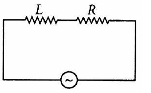
Step Solution:
1. Analyze Purely Resistive Case: For a resistor alone, Power $P = \frac{V^2}{R}$, which implies $V^2 = PR$.
2. State Power Formula for LR Circuit: $P' = V I \cos \phi$.
3. Substitute Current and Power Factor: $P' = V \times (\frac{V}{Z}) \times (\frac{R}{Z}) = \frac{V^2 R}{Z^2}$.
4. Substitute $V^2$ from Step 1: Replace $V^2$ with $PR$ to get $P' = \frac{(PR)R}{Z^2}$.
5. Simplify: $P' = P (\frac{R^2}{Z^2}) = P(\frac{R}{Z})^2$.
The difficulty level: Medium
The Concept Name: Power in AC Circuits.
Short cut solution: Power in any AC circuit is $I^2 R$. Initially $I = V/R$, so $P = (V/R)^2 R$. Finally $I' = V/Z$, so $P' = (V/Z)^2 R$. The ratio $P'/P = (V/Z)^2 / (V/R)^2 = R^2 / Z^2$. Thus, $P' = P(R/Z)^2$.
Question 49
Question: A series R-C circuit is connected to an alternating voltage source. Consider two situations: (a) When capacitor is air filled. (b) When capacitor is mica filled. Current through resistor is $i$ and voltage across capacitor is $V$ then.
Options:
A. $i_a > i_b$
B. $V_a = V_b$
C. $V_a < V_b$
D. $V_a > V_b$
Correct Answer: D
Year: 2015
Solution (as Given in the Source): $i = \frac{V_0}{\sqrt{R^2 + (1/\omega C)^2}}$. $V = i X_C = \frac{V_0}{\sqrt{R^2 + (1/\omega C)^2}} \times \frac{1}{\omega C} = \frac{V_0}{\sqrt{R^2 \omega^2 C^2 + 1}}$. $C_a < C_b \therefore i_a < i_b$ and $V_a > V_b$.
Step Solution:
1. Compare Capacitance: Mica has a higher dielectric constant than air, so $C_b > C_a$.
2. Determine Current Behavior: Since $i = \frac{V}{\sqrt{R^2 + X_C^2}}$ and $X_C = \frac{1}{\omega C}$, a larger $C$ means a smaller $X_C$ and thus a higher current ($i_b > i_a$).
3. Express Capacitor Voltage: $V_C = i X_C = \frac{V_0}{\sqrt{R^2 + (1/\omega C)^2}} \cdot \frac{1}{\omega C} = \frac{V_0}{\sqrt{R^2 \omega^2 C^2 + 1}}$.
4. Analyze Voltage Dependency: In the expression $\frac{V_0}{\sqrt{R^2 \omega^2 C^2 + 1}}$, the capacitance $C$ is in the denominator.
5. Conclude: Because $C_b > C_a$, the denominator for situation (b) is larger, resulting in a smaller voltage ($V_b < V_a$).
The difficulty level: Hard
The Concept Name: RC Circuit Analysis with Dielectrics.
Short cut solution: Adding a dielectric (mica) increases $C$, which decreases $X_C$. As $X_C$ decreases, the capacitor's share of the total voltage drop in the series circuit decreases. Therefore, $V_{mica} < V_{air}$, or $V_a > V_b$.
Question 54
Question: A coil of self-inductance L is connected in series with a bulb B and an AC source. Brightness of the bulb decreases when
Options:
A. a capacitance of reactance $X_C = X_L$ is included in the same circuit.
B. an iron rod is inserted in the coil.
C. frequency of the A C source is decreased.
D. number of turns in the coil is reduced.
Correct Answer: B
Year: 2013 NEET
Solution (as Given in the Source): As the iron rod is inserted, the magnetic field inside the coil magnetizes the iron increasing the magnetic field inside it. Hence, the inductance of the coil increases. Consequently, the inductive reactance of the coil increases. As a result, a larger fraction of the applied AC voltage appears across the inductor, leaving less voltage across the bulb. Therefore, the brightness of the light bulb decreases.
Step Solution:
1. Analyze Inductance Change: Inserting an iron rod increases the magnetic permeability, which increases the self-inductance ($L$) of the coil.
2. Determine Reactance: Inductive reactance $X_L = 2\pi f L$. Since $L$ increased, $X_L$ also increases.
3. Calculate Total Impedance: In a series circuit, total impedance $Z = \sqrt{R^2 + X_L^2}$ increases due to the higher $X_L$.
4. Find Current Flow: According to Ohm's Law for AC ($I = V/Z$), an increase in impedance leads to a decrease in the circuit current.
5. Evaluate Brightness: Bulb brightness depends on power ($P = I^2 R$). As the current $I$ decreases, the power and thus the brightness of the bulb decrease.
The difficulty level: Medium
The Concept Name: Inductive Reactance and Inductance.
Short cut solution: Iron rod $\rightarrow$ Increase in $L$ $\rightarrow$ Increase in $X_L$ $\rightarrow$ Decrease in circuit current $\rightarrow$ Decrease in bulb brightness.
Question 55
Question: In an electrical circuit, R, L, C and ac voltage source are all connected in series. When L is removed from the circuit, the phase difference between the voltage and the current in the circuit is $\pi/3$. If instead, C is removed from the circuit, the phase difference is again $\pi/3$. The power factor of the circuit is
Options:
A. 1/2
B. 1/$\sqrt{2}$
C. 1
D. $\sqrt{3}/2$
Correct Answer: C
Year: 2012
Solution (as Given in the Source): When L is removed, $\tan \phi_1 = \frac{X_C}{R}, \tan \frac{\pi}{3} = \frac{X_C}{R} \Rightarrow X_C = \sqrt{3}R$. When C is removed, $\tan \phi_2 = \frac{X_L}{R}, \tan \frac{\pi}{3} = \frac{X_L}{R} \Rightarrow X_L = \sqrt{3} R$. As $X_L = X_C$, the series LCR circuit is in resonance. $Z = \sqrt{R^2 + (X_L - X_C)^2} = R$. Power factor, $\cos \phi = \frac{R}{Z} = \frac{R}{R} = 1$.
Step Solution:
1. Analyze situation (a): With L removed, the circuit is an RC circuit. The phase angle $\tan(\pi/3) = X_C / R$, so $X_C = R\sqrt{3}$.
2. Analyze situation (b): With C removed, the circuit is an RL circuit. The phase angle $\tan(\pi/3) = X_L / R$, so $X_L = R\sqrt{3}$.
3. Compare Reactances: Since both equal $R\sqrt{3}$, we find $X_L = X_C$.
4. Identify State: When $X_L = X_C$, the circuit is in resonance, and impedance $Z$ equals resistance $R$.
5. Calculate Power Factor: Power factor $\cos \phi = R/Z = R/R = 1$.
The difficulty level: Medium
The Concept Name: Resonance in LCR Circuits.
Short cut solution: If the phase angle remains the same when either L or C is removed, then $X_L = X_C$. This means the circuit is at resonance, and the power factor at resonance is always 1.
Question 57
Question: The instantaneous values of alternating current and voltages in a circuit are given as $i = \frac{1}{\sqrt{2}} \sin(100\pi t) \text{ ampere}$ and $e = \frac{1}{\sqrt{2}} \sin(100\pi t + \frac{\pi}{3}) \text{ Volt}$. The average power in watts consumed in the circuit is
Options:
A. 1/4
B. $\sqrt{3}/4$
C. 1/2
D. 1/8
Correct Answer: D
Year: 2012 Mains
Solution (as Given in the Source): $i_0 = \frac{1}{\sqrt{2}} \text{ A}, e_0 = \frac{1}{\sqrt{2}} \text{ V}, \phi = \frac{\pi}{3}$. $i_{rms} = \frac{i_0}{\sqrt{2}} = \frac{1/ \sqrt{2}}{\sqrt{2}} = \frac{1}{2} \text{ A}$, $e_{rms} = \frac{e_0}{\sqrt{2}} = \frac{1/ \sqrt{2}}{\sqrt{2}} = \frac{1}{2} \text{ V}$. Average power $P = i_{rms} e_{rms} \cos \phi = (\frac{1}{2})(\frac{1}{2}) \cos \frac{\pi}{3} = (\frac{1}{2})(\frac{1}{2})(\frac{1}{2}) = \frac{1}{8} \text{ W}$.
Step Solution:
1. Identify Peak Values: From the equations, peak current $i_0 = 1/\sqrt{2}$ A and peak voltage $e_0 = 1/\sqrt{2}$ V.
2. Calculate RMS Values: $I_{rms} = \frac{i_0}{\sqrt{2}} = \frac{1}{2}$ A and $E_{rms} = \frac{e_0}{\sqrt{2}} = \frac{1}{2}$ V.
3. Identify Phase Difference: The phase angle $\phi$ between voltage and current is $\pi/3$.
4. Use Power Formula: Average power $P = E_{rms} I_{rms} \cos \phi$.
5. Calculate Result: $P = (1/2) \times (1/2) \times \cos(60^\circ) = 1/4 \times 1/2 = 1/8$ W.
The difficulty level: Easy
The Concept Name: Average Power in AC Circuits.
Short cut solution: Average power $P = \frac{e_0 i_0}{2} \cos \phi$. Substituting the peak values: $\frac{(1/\sqrt{2}) \times (1/\sqrt{2})}{2} \times \cos(60^\circ) = \frac{0.5}{2} \times 0.5 = 1/8$ W.
Question 61
Question: An ac voltage is applied to a resistance R and an inductor L, in series. If R and the inductive reactance are both equal to 3Ω, the phase difference between the applied voltage and the current in the circuit is
Options:
A. $\pi/6$
B. $\pi/4$
C. $\pi/2$
D. zero
Correct Answer: B
Year: 2011
Solution (as Given in the Source): Here, $R = 3 \Omega$. Inductive reactance, $X_L = 3 \Omega$. The phase difference between the applied voltage and the current in the circuit is $\tan \phi = \frac{X_L}{R} = \frac{3 \Omega}{3 \Omega} = 1 \Rightarrow \phi = \tan^{-1}(1)$ or $\phi = \frac{\pi}{4}$.
Step Solution:
1. Identify Given Values: Resistance $R = 3 \Omega$ and inductive reactance $X_L = 3 \Omega$.
2. State the Phase Formula: For a series RL circuit, the phase difference $\phi$ is given by $\tan \phi = \frac{X_L}{R}$.
3. Substitute Values: $\tan \phi = \frac{3}{3} = 1$.
4. Solve for $\phi$: $\phi = \tan^{-1}(1)$.
5. Calculate Final Angle: Since $\tan(45^\circ) = 1$, the angle is $45^\circ$ or $\frac{\pi}{4}$ radians.
The difficulty level: Easy
The Concept Name: Phase Difference in an RL Circuit.
Short cut solution: In any series circuit, if the resistance equals the reactance ($R = X$), the phase angle is always $45^\circ$ ($\pi/4$).
Question 62
Question: In an ac circuit, an alternating voltage $e = 200\sqrt{2}\sin 100t$ volts is connected to a capacitor of capacity $1\mu F$. The r.m.s. value of the current in the circuit is
Options:
A. 10 mA
B. 100 mA
C. 200 mA
D. 20 mA
Correct Answer: D
Year: 2011
Solution (as Given in the Source): $e_0 = 200\sqrt{2}$ V, $\omega = 100$ rad/s. $X_C = \frac{1}{\omega C} = \frac{1}{100 \times 1 \times 10^{-6}} \Omega$. $i_{r.m.s} = \frac{v_{r.m.s}}{X_C} = \frac{e_0/\sqrt{2}}{1/\omega C} = \frac{200\sqrt{2}/\sqrt{2}}{1/100 \times 10^{-6}} = 200 \times 100 \times 10^{-6} \text{ A} = 2 \times 10^{-2} \text{ A} = 20 \text{ mA}$.
Step Solution:
1. Extract Voltage Parameters: From $e = 200\sqrt{2}\sin 100t$, peak voltage $e_0 = 200\sqrt{2}$ V and angular frequency $\omega = 100$ rad/s.
2. Calculate RMS Voltage: $V_{rms} = \frac{e_0}{\sqrt{2}} = \frac{200\sqrt{2}}{\sqrt{2}} = 200$ V.
3. Calculate Capacitive Reactance ($X_C$): $X_C = \frac{1}{\omega C} = \frac{1}{100 \times 10^{-6}} = 10^4 \Omega$.
4. Apply Ohm's Law for RMS current: $I_{rms} = \frac{V_{rms}}{X_C}$.
5. Final Calculation: $I_{rms} = \frac{200}{10000} = 0.02$ A, which equals 20 mA.
The difficulty level: Medium
The Concept Name: RMS Current and Capacitive Reactance.
Short cut solution: Use $I_{rms} = V_{rms} \cdot \omega \cdot C$. Since $V_{rms} = 200$ and $\omega \cdot C = 10^{-4}$, the current is $200 \times 10^{-4} = 0.02 \text{ A} = 20 \text{ mA}$.
Question 64
Question: The rms value of potential difference V shown in the figure is
Options:
A. $V_0/\sqrt{3}$
B. $V_0$
C. $V_0/\sqrt{2}$
D. $V_0/2$
Correct Answer: C
Year: 2011 Mains
Solution (as Given in the Source): $V = V_0$ for $0 \leq t \leq T/2$ and $V = 0$ for $T/2 \leq t \leq T$. $V_{rms} = [\frac{\int_0^T V^2 dt}{\int_0^T dt}]^{1/2} = [\frac{\int_0^{T/2} V_0^2 dt + \int_{T/2}^T (0) dt}{T}]^{1/2} = [ \frac{V_0^2}{T} (\frac{T}{2}) ]^{1/2} = [ \frac{V_0^2}{2} ]^{1/2} = \frac{V_0}{\sqrt{2}}$.
Step Solution:
1. Define Voltage Function: The wave is $V_0$ for half the period ($T/2$) and zero for the other half.
2. Apply RMS Formula: $V_{rms} = \sqrt{\frac{1}{T} \int_0^T V^2(t) dt}$.
3. Split the Integral: $V_{rms} = \sqrt{\frac{1}{T} [\int_0^{T/2} V_0^2 dt + \int_{T/2}^T 0 dt]}$.
4. Evaluate Integral: The integral of $V_0^2$ from $0$ to $T/2$ is $V_0^2 \cdot (T/2)$.
5. Simplify: $V_{rms} = \sqrt{\frac{V_0^2 \cdot T}{2T}} = \sqrt{\frac{V_0^2}{2}} = \frac{V_0}{\sqrt{2}}$.
The difficulty level: Hard
The Concept Name: RMS Value of a Square Wave Pulse.
Short cut solution: For a periodic square pulse with a 50% duty cycle (on for half the time), the RMS value is always the peak value divided by $\sqrt{2}$.
Question 65
Question: A coil has resistance 30 ohm and inductive reactance 20 ohm at 50 Hz frequency. If an ac source, of 200 volt, 100 Hz, is connected across the coil, the current in the coil will be.
Options:
A. 2.0 A
B. 4.0 A
C. 8.0 A
D. $\frac{20}{\sqrt{13}}$ A
Correct Answer: B
Year: 2011 Mains
Solution (as Given in the Source): Here Resistance $R = 30 \Omega$. Inductive reactance $X_L = 20 \Omega$ at 50 Hz. Since $X_L = 2\pi\nu L$, then $\frac{X_L}{X_L'} = \frac{\nu}{\nu'}$. $X_L' = (\frac{100}{50}) \times 20 \Omega = 40 \Omega$. Impedance $Z = \sqrt{R^2 + (X_L')^2} = \sqrt{30^2 + 40^2} = 50 \Omega$. Current in the coil $I = \frac{V}{Z} = \frac{200 V}{50 \Omega} = 4 A$.
Step Solution:
1. Find new inductive reactance ($X_L'$): Since $X_L \propto f$, doubling frequency from 50 Hz to 100 Hz doubles the reactance from $20 \Omega$ to $40 \Omega$.
2. State Resistance: The resistance $R$ remains constant at $30 \Omega$.
3. Calculate Total Impedance ($Z$): $Z = \sqrt{R^2 + (X_L')^2} = \sqrt{30^2 + 40^2}$.
4. Math Simplification: $Z = \sqrt{900 + 1600} = \sqrt{2500} = 50 \Omega$.
5. Calculate Current ($I$): $I = V / Z = 200 / 50 = 4$ A.
The difficulty level: Medium
The Concept Name: Inductive Reactance and Impedance.
Short cut solution: Frequency doubles $\implies X_L$ doubles ($20 \to 40 \Omega$). For a 30-40-50 triangle, impedance $Z = 50 \Omega$. $I = 200/50 = 4$ A.
Question 67
Question: In the given circuit, the reading of voltmeter $V_{\lambda_1}$ and $V_2$ are 300 volts each. The reading of the voltmeter $V_3$ and ammeter A are respectively.
Options:
A. 150 V, 2.2 A
B. 220 V, 2.2 A
C. 220 V, 2.0 A
D. 100 V, 2.0 A
Correct Answer: B
Year: 2010
Solution (as Given in the Source): As $V_L = V_C = 300$ V, therefore the given series LCR circuit is in resonance. $\therefore V_R = V = 220$ V and $Z = R = 100 \Omega$. Current $I = V / Z = 220 V / 100 \Omega = 2.2$ A. Hence, the reading of the voltmeter $V_3$ is 220 V and the reading of ammeter A is 2.2 A.
Step Solution:
1. Identify resonance: Because the voltages across the inductor ($V_L$) and capacitor ($V_C$) are equal at 300 V, the circuit is at resonance.
2. Determine Voltmeter $V_3$ reading: At resonance, the voltage across the resistor is equal to the total supply voltage, which is 220 V.
3. Identify Resistance: The circuit resistance $R$ is $100 \Omega$.
4. Determine Impedance: At resonance, $Z = R = 100 \Omega$.
5. Calculate Current ($I$): $I = V / R = 220 / 100 = 2.2$ A.
The difficulty level: Easy
The Concept Name: Resonance in Series LCR Circuit.
Short cut solution: $V_L = V_C \implies$ resonance. In resonance, $V_R = V_{total} = 220$ V. Only options B and C have 220 V. $I = V/R = 220/100 = 2.2$ A.
Question 69
Question: A condenser of capacity C is charged to a potential difference of $V_1$. The plates of the condenser are then connected to an ideal inductor of inductance L. The current through the inductor when the potential difference across the condenser reduces to $V_2$ is.
Options:
A. $C(V_1 - V_2)^2 (2L^2)^{1/2}$
B. $C(V_1^2 - V_2^2) / L$
C. $C(V_1^2 + V_2^2) / L$
D. $[C(V_1^2 - V_2^2) / L]^{1/2}$
Correct Answer: D
Year: 2010 Mains
Solution (as Given in the Source): In case of oscillatory discharge of a capacitor through an inductor, charge at instant $t$ is $q = q_0 \cos \omega t$ where $\omega = 1/\sqrt{LC}$. $\cos \omega t = q/q_0 = CV_2/CV_1 = V_2/V_1$. Current $I = dq/dt = -q_0 \omega \sin \omega t$. $|I| = CV_1 (1/\sqrt{LC}) [1 - \cos^2 \omega t]^{1/2} = V_1 \sqrt{C/L} [1 - (V_2/V_1)^2]^{1/2} = [C(V_1^2 - V_2^2)/L]^{1/2}$.
Step Solution:
1. Use Conservation of Energy: Total initial energy in the capacitor must equal the sum of remaining capacitor energy and inductor energy.
2. Set up Equation: $\frac{1}{2} C V_1^2 = \frac{1}{2} C V_2^2 + \frac{1}{2} L I^2$.
3. Isolate Inductor Term: $\frac{1}{2} L I^2 = \frac{1}{2} C V_1^2 - \frac{1}{2} C V_2^2$.
4. Solve for $I^2$: $I^2 = \frac{C (V_1^2 - V_2^2)}{L}$.
5. Final Calculation: $I = \sqrt{\frac{C (V_1^2 - V_2^2)}{L}}$.
The difficulty level: Hard
The Concept Name: LC Oscillations (Energy Conservation).
Short cut solution: Apply energy conservation: Initial Energy = Final Energy. $\frac{1}{2} C V_1^2 = \frac{1}{2} C V_2^2 + \frac{1}{2} L I^2$. Quick rearrangement gives $I = \sqrt{\frac{C(V_1^2 - V_2^2)}{L}}$.
Question 71
Question: Power dissipated in an LCR series circuit connected to an A.C. source of emf $\varepsilon$ is
Options:
A. $\frac{\varepsilon^2 \sqrt{R^2 + (L\omega - \frac{1}{C\omega})^2}}{R}$
B. $\frac{\varepsilon^2 [R^2 + (L\omega - \frac{1}{C\omega})^2]}{R}$
C. $\frac{\varepsilon^2 R}{\sqrt{R^2 + (L\omega - \frac{1}{C\omega})^2}}$
D. $\frac{\varepsilon^2 R}{R^2 + (L\omega - \frac{1}{C\omega})^2}$
Correct Answer: D
Year: 2009
Solution (as Given in the Source): Average power, $P = E_{rms} I_{rms} \cos \phi$. $Z = \sqrt{R^2 + (X_L - X_C)^2}, \cos \phi = \frac{R}{Z}$. But $I_{rms} = \frac{E_{rms}}{Z}$. $\therefore P = E_{rms}^2 \cdot \frac{R}{Z^2}$.
Step Solution:
1. Define average power in an AC circuit: $P = \varepsilon_{rms} I_{rms} \cos \phi$.
2. Substitute RMS current ($I_{rms} = \frac{\varepsilon}{Z}$) and Power Factor ($\cos \phi = \frac{R}{Z}$): $P = \varepsilon \times (\frac{\varepsilon}{Z}) \times (\frac{R}{Z}) = \frac{\varepsilon^2 R}{Z^2}$.
3. State the formula for Impedance ($Z$): $Z = \sqrt{R^2 + (X_L - X_C)^2}$.
4. Express Reactances: $X_L = L\omega$ and $X_C = \frac{1}{C\omega}$.
5. Final Substitution: $P = \frac{\varepsilon^2 R}{R^2 + (L\omega - \frac{1}{C\omega})^2}$.
The difficulty level: Medium
The Concept Name: Power in AC Circuits (LCR Series).
Short cut solution: Real power is only dissipated by the resistor: $P = I_{rms}^2 R$. Since $I_{rms} = \frac{V}{Z}$, the power is $(\frac{V}{Z})^2 R = \frac{V^2 R}{Z^2}$.
Question 74
Question: In an a.c. circuit, the e.m.f ($\varepsilon$) and the current ($i$) at any instant are given respectively by $\varepsilon = E_0 \sin \omega t, i = I_0 \sin (\omega t - \phi)$. The average power in the circuit over one cycle of a.c. is
Options:
A. $\frac{E_0 I_0}{2} \cos \phi$
B. $E_0 I_0$
C. $\frac{E_0 I_0}{2}$
D. $\frac{E_0 I_0}{2} \sin \phi$
Correct Answer: A
Year: 2008
Solution (as Given in the Source): Average power = $\frac{E_0 I_0 \cos \phi}{2}$.
Step Solution:
1. Recall the definition of average power: $P_{avg} = V_{rms} I_{rms} \cos \phi$.
2. Convert peak values to RMS values: $V_{rms} = \frac{E_0}{\sqrt{2}}$ and $I_{rms} = \frac{I_0}{\sqrt{2}}$.
3. Substitute RMS values into the power formula: $P_{avg} = (\frac{E_0}{\sqrt{2}}) \times (\frac{I_0}{\sqrt{2}}) \times \cos \phi$.
4. Perform multiplication: $\sqrt{2} \times \sqrt{2} = 2$ in the denominator.
5. State the result: $P_{avg} = \frac{E_0 I_0}{2} \cos \phi$.
The difficulty level: Easy
The Concept Name: Average Power in AC Circuits.
Short cut solution: Average power is always the product of RMS voltage, RMS current, and the power factor. $\frac{E_0}{\sqrt{2}} \times \frac{I_0}{\sqrt{2}} \times \cos \phi = \frac{E_0 I_0}{2} \cos \phi$.
Question 78
Question: What is the value of inductance L for which the current is maximum in a series LCR circuit with $C = 10 \mu F$ and $\omega = 1000 s^{-1}$?
Options:
A. 1 mH
B. cannot be calculated unless R is known
C. 10 mH
D. 100 mH
Correct Answer: D
Year: 2007
Solution (as Given in the Source): In series LCR, current is maximum at resonance. $\therefore$ Resonant frequency $\omega = \frac{1}{\sqrt{LC}} \Rightarrow L = \frac{1}{\omega^2 C}$. Given $\omega = 1000 \text{ s}^{-1}$ and $C = 10 \mu F \Rightarrow L = \frac{1}{1000 \times 1000 \times 10 \times 10^{-6}} = 0.1 H = 100 mH$.
Step Solution:
1. Identify the condition for maximum current: Current is maximum when the circuit is in resonance.
2. State the resonance condition: $\omega = \frac{1}{\sqrt{LC}}$.
3. Rearrange the formula to solve for Inductance ($L$): $L = \frac{1}{\omega^2 C}$.
4. Substitute the given numerical values: $L = \frac{1}{(1000)^2 \times (10 \times 10^{-6})}$.
5. Perform the calculation: $L = \frac{1}{10^6 \times 10^{-5}} = \frac{1}{10} = 0.1 \text{ H}$, which converts to 100 mH.
The difficulty level: Easy
The Concept Name: Resonance in Series LCR Circuits.
Short cut solution: Use the formula $L = \frac{1}{\omega^2 C}$. With $\omega = 10^3$ and $C = 10^{-5}$, $L$ is simply the reciprocal of $10^6 \times 10^{-5} = 10$, giving $0.1 \text{ H} = 100 \text{ mH}$.
Question 79
Question: A coil of inductive reactance 31$\Omega$ has a resistance of 8$\Omega$. It is placed in series with a condenser of capacitative reactance 25$\Omega$. The combination is connected to an a.c. source of 110 V. The power factor of the circuit is
Options:
A. 0.33
B. 0.56
C. 0.64
D. 0.80
Correct Answer: D
Year: 2006
Solution (as Given in the Source): $X_L = 31 \Omega, X_C = 25 \Omega, R = 8 \Omega$. Impedance of series LCR is $Z = \sqrt{(R^2) + (X_L - X_C)^2} = \sqrt{(8)^2 + (31 - 25)^2} = \sqrt{64 + 36} = 10 \Omega$. Power factor, $\cos \phi = R / Z = 8 / 10 = 0.8$.
Step Solution:
1. Identify parameters: $R = 8 \Omega$, $X_L = 31 \Omega$, and $X_C = 25 \Omega$.
2. Calculate net reactance ($X$): $X = X_L - X_C = 31 - 25 = 6 \Omega$.
3. State Impedance formula: $Z = \sqrt{R^2 + X^2}$.
4. Calculate $Z$: $Z = \sqrt{8^2 + 6^2} = \sqrt{64 + 36} = 10 \Omega$.
5. Calculate Power Factor: $\cos \phi = R / Z = 8 / 10 = 0.8$.
The difficulty level: Easy
The Concept Name: Power Factor in an LCR Circuit.
Short cut solution: Recognize the 6-8-10 Pythagorean triple. Since Resistance is 8 and net Reactance is 6, the Impedance must be 10. Power factor is simply $8/10 = 0.8$.
Question 82
Question: A transistor-oscillator using a resonant circuit with an inductor L (of negligible resistance) and a capacitor C in series produce oscillations of frequency f. If L is doubled and C is changed to 4C, the frequency will be
Options:
A. [Not provided in source]
B. f
C. 8f
D. $f / 2\sqrt{2}$
Correct Answer: D
Year: 2006
Solution (as Given in the Source): Frequency of LC oscillation $= \frac{1}{2 \pi \sqrt{L C}}$. or, $\frac{f_1}{f_2} = \left(\frac{L_2 C_2}{L_1 C_1}\right)^{1 / 2} = \left(\frac{2 L \times 4 C}{L \times C}\right)^{\frac{1}{2}} = (8)^{1 / 2}$. $\therefore \frac{f_1}{f_2} = 2 \sqrt{2} \Rightarrow f_2 = \frac{f_1}{2 \sqrt{2}}$ or $f_2 = \frac{f}{2 \sqrt{2}}$.
Step Solution:
1. State the frequency formula: $f = \frac{1}{2\pi\sqrt{LC}}$.
2. Identify proportionality: Frequency $f$ is inversely proportional to the square root of the product $LC$.
3. Apply the changes: New inductance $L' = 2L$ and new capacitance $C' = 4C$.
4. Calculate new $LC$ product: $L'C' = (2L)(4C) = 8LC$.
5. Find new frequency ($f'$): $f' \propto \frac{1}{\sqrt{8LC}} = \frac{1}{\sqrt{8}} f = \frac{f}{2\sqrt{2}}$.
The difficulty level: Medium
The Concept Name: Resonant Frequency of an LC Circuit.
Short cut solution: The product of $L$ and $C$ increases by a factor of 8 ($2 \times 4$). Since frequency is $1/\sqrt{\text{product}}$, the new frequency is $1/\sqrt{8} = 1/2\sqrt{2}$ times the original.
Question 83
Question: In a circuit L, C and R are connected in series with an alternating voltage source of frequency f. The current leads the voltage by $45^\circ$. The value of C is
Options:
A. $\frac{1}{\pi f (2 \pi f L - R)}$
B. $\frac{1}{2 \pi f (2 \pi f L - R)}$
C. $\frac{1}{\pi f (2 \pi f L + R)}$
D. $\frac{1}{2 \pi f (2 \pi f L + R)}$
Correct Answer: D
Year: 2005
Solution (as Given in the Source): $\tan \phi = \frac{X_C - X_L}{R}$. $\tan \left(\frac{\pi}{4}\right) = \frac{\frac{1}{\omega C} - \omega L}{R}$. $R = \frac{1}{\omega C} - \omega L$. $(R + 2 \pi f L) = \frac{1}{2 \pi f C}$ or $C = \frac{1}{2 \pi f (R + 2 \pi f L)}$.
Step Solution:
1. Use the phase formula: For current leading voltage, $\tan \phi = \frac{X_C - X_L}{R}$.
2. Substitute the angle: Since $\phi = 45^\circ$, $\tan(45^\circ) = 1$, which gives $1 = \frac{X_C - X_L}{R}$, or $R = X_C - X_L$.
3. Rearrange for $X_C$: $X_C = R + X_L$.
4. Substitute component values: $\frac{1}{2\pi f C} = R + 2\pi f L$.
5. Isolate $C$: $C = \frac{1}{2\pi f (R + 2\pi f L)}$.
The difficulty level: Hard
The Concept Name: Phase Angle in a Series LCR Circuit.
Short cut solution: A phase lead of $45^\circ$ means $X_C - X_L = R$. This implies $X_C = R + X_L$. Plugging in the expressions for reactances ($1/\omega C$ and $\omega L$) immediately leads to Option D.
Question 87
Question: For a series LCR circuit the power loss aresonance is
Options:
A. $V^2 [ \omega L - \frac{1}{\omega C} ]$
B. $I^2 L \omega$
C. $I^2 R$
D. $V^2 C \omega$
Correct Answer: C
Year: 2002
Solution (as Given in the Source): The impedance $Z$ of a series LCR circuit is given by, $Z = \sqrt{R^2 + (X_L - X_C)^2}$ where $X_L = \omega L$ and $X_C = \frac{1}{\omega C}$, $\omega$ is angular frequency. At resonance, $X_L = X_C$, hence $Z = R$. $\therefore V_R = V$ (supply voltage). $\therefore$ R.M.S. current, $I = \frac{V}{R} = \frac{V}{R}$. $\therefore$ Power loss $= I^2 R = \frac{V^2}{R}$.
Step Solution:
1. State the Impedance formula: $Z = \sqrt{R^2 + (X_L - X_C)^2}$.
2. Apply resonance condition: At resonance, $X_L = X_C$, meaning the reactive components cancel each other out.
3. Determine simplified Impedance: Because reactances cancel, $Z = R$.
4. Define Power Loss: In an AC circuit, real power is dissipated only by the resistance, given by $P = I^2 R$.
5. Finalize: Since the circuit acts as a pure resistor at resonance, the power loss is $I^2 R$.
The difficulty level: Easy
The Concept Name: Resonance in Series LCR Circuits.
Short cut solution: At resonance, $X_L$ and $X_C$ are equal and opposite, effectively removing them from the power calculation. The circuit becomes purely resistive, and power in a resistor is always $I^2 R$.
Question 89
Question: A capacitor of capacity C has reactance X. If capacitance and frequency become double then reactance will be
Options:
A. $4X$
B. $X/2$
C. $X/4$
D. $2X$
Correct Answer: C
Year: 2001
Solution (as Given in the Source): $X = \frac{1}{C \omega}$, $X' = \frac{1}{4 C \omega}$. $\therefore X' = \frac{X}{4}$.
Step Solution:
1. Define initial reactance ($X$): $X = \frac{1}{2\pi f C}$, where $f$ is frequency and $C$ is capacitance.
2. Identify changes: New frequency $f' = 2f$ and new capacitance $C' = 2C$.
3. Set up new reactance formula ($X'$): $X' = \frac{1}{2\pi (2f) (2C)}$.
4. Simplify the expression: $X' = \frac{1}{4 (2\pi f C)}$.
5. Substitute the original value: Since $\frac{1}{2\pi f C} = X$, then $X' = \frac{X}{4}$.
The difficulty level: Easy
The Concept Name: Capacitive Reactance.
Short cut solution: Capacitive reactance is inversely proportional to the product of frequency and capacitance ($X_C \propto \frac{1}{fC}$). If both $f$ and $C$ are doubled, the product increases by 4, making the reactance $\frac{1}{4}$ of its original value.
Question 90
Question: The value of quality factor is
Options:
A. $\frac{\omega L}{R}$
B. $\frac{1}{\omega RC}$
C. $\sqrt{LC}$
D. $\frac{L}{R}$
Correct Answer: B
Year: 2000
Solution (as Given in the Source): Quality factor $Q = \frac{\omega L}{R}$. since $\omega^2 = \frac{1}{LC}$. $\therefore$ Quality factor $Q = \frac{1}{\omega RC}$.
Step Solution:
1. State the standard definition of $Q$: $Q = \frac{\omega L}{R}$.
2. Recall the resonance relationship: $\omega^2 = \frac{1}{LC}$.
3. Isolate Inductance ($L$): From the resonance formula, $L = \frac{1}{\omega^2 C}$.
4. Substitute $L$ into the $Q$ formula: $Q = \frac{\omega (\frac{1}{\omega^2 C})}{R}$.
5. Simplify: The $\omega$ in the numerator cancels one in the denominator, resulting in $Q = \frac{1}{\omega RC}$.
The difficulty level: Medium
The Concept Name: Quality Factor (Q-factor).
Short cut solution: The Quality factor is the ratio of the reactance of either the inductor or capacitor to the resistance at resonance. Therefore, $Q = \frac{X_L}{R} = \frac{\omega L}{R}$ OR $Q = \frac{X_C}{R} = \frac{1}{\omega RC}$. Option B matches the latter form.
Question 91
Question: In the circuit given in figure, 1 and 2 are ammeters. Just after key K is pressed to complete the circuit, the reading will be.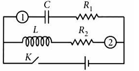
Options:
A. zero in 1, maximum in 2
B. maximum in both 1 and 2
C. zero in both 1 and 2
D. maximum in 1, zero in 2.
Correct Answer: D.
Year: 1999.
Solution (as Given in the Source): At $t = 0$, (i) capacitor offers negligible resistance, (ii) inductor offers large resistance to current flow.
Step Solution:
1. Analyze Inductor Behavior: At the instant the key is pressed ($t = 0$), an inductor opposes the sudden change in current by offering an extremely large (infinite) resistance.
2. Determine Inductor Current: Because of this large resistance, ammeter 2, which is in series with the inductor, will show a reading of zero.
3. Analyze Capacitor Behavior: At $t = 0$, a capacitor offers negligible resistance, acting essentially as a short circuit.
4. Determine Capacitor Current: Because the resistance is negligible, the current through ammeter 1, which is in series with the capacitor, will be at its maximum.
5. Conclusion: The reading is maximum in ammeter 1 and zero in ammeter 2.
The difficulty level: Medium.
The Concept Name: Transient Response of Inductors and Capacitors.
Short cut solution: At $t = 0$, an inductor acts as an open circuit (zero current) and a capacitor acts as a short circuit (maximum current).
Question 95
Question: In an a.c. circuit with phase voltage V and current I, the power dissipated is.
Options:
A. V . I
B. depends on phase angle between V and I
C. 1/2 × V . I
D. $1/\sqrt{2} \times V . I$.
Correct Answer: B.
Year: Not explicitly provided in the source for this specific question.
Solution (as Given in the Source): The dissipation of power in an a.c. circuit is $(P) = V \times I \times \cos \theta$. Therefore current flowing in the circuit depends upon the phase angle between voltage (V) and current (I) of the a.c. circuit.
Step Solution:
1. State the Power Formula: In an AC circuit, average power dissipation is $P = V I \cos \theta$, where $V$ and $I$ are RMS values.
2. Identify the Phase Angle: The term $\theta$ represents the phase difference between the voltage and the current.
3. Analyze the Power Factor: The term $\cos \theta$ is the power factor, which scales the product of $V$ and $I$.
4. Evaluate Dependency: Because $P$ is a direct function of $\cos \theta$, the actual power dissipated changes as the angle $\theta$ changes.
5. Conclusion: Power dissipation depends on the phase angle between $V$ and $I$.
The difficulty level: Easy.
The Concept Name: Average Power in AC Circuits.
Short cut solution: Power $= VI \cos \theta$; therefore, power dissipation is inherently dependent on the phase angle $\theta$.
Question 97
Question: In an A.C. circuit, the current flowing is $I = 5 \sin(100t - \pi/2)$ ampere and the potential difference is $V = 200 \sin(100t)$ volts. The power consumption is equal to.
Options:
A. 20 W
B. 0 W
C. 1000 W
D. 40 W.
Correct Answer: B.
Year: 1995.
Solution (as Given in the Source): Current $(I) = 5 \sin(100t - \pi/2)$ and voltage $(V) = 200 \sin(100t)$. Comparing the given equation with the standard equation, we find that phase between current and voltage is $\phi = \pi/2 = 90^\circ$. Power consumption $P = I_{rms} V_{rms} \cos \phi = I_{rms} V_{rms} \cos 90^\circ = 0$.
Step Solution:
1. Extract Phase Information: Compare the current $I = 5 \sin(100t - \pi/2)$ and voltage $V = 200 \sin(100t)$ to find the phase difference.
2. Identify the Angle: The phase difference $\phi$ is $\pi/2$ radians, which is $90^\circ$.
3. State the Power Formula: Power consumption is $P = V_{rms} I_{rms} \cos \phi$.
4. Determine Power Factor: Calculate $\cos(90^\circ)$, which equals 0.
5. Final Calculation: $P = V_{rms} I_{rms} \times 0 = 0$ W.
The difficulty level: Easy.
The Concept Name: Wattless Current / Power Factor.
Short cut solution: Since the phase difference between current and voltage is exactly $90^\circ$, the power factor ($\cos 90^\circ$) is zero, making power consumption zero.
Question 101
Question: In an A.C. circuit, $I_{rms}$ and $I_0$ are related as
Options:
A. $I_{rms} = \pi I_0$
B. $I_{rms} = \sqrt{2} I_0$
C. $I_{rms} = \frac{I_0}{\pi}$
D. $I_{rms} = \frac{I_0}{\sqrt{2}}$
Correct Answer: D
Year: Not specified in source.
Solution (as Given in the Source): $I_{rms} = \frac{I_0}{\sqrt{2}}$
Step Solution:
1. Define peak value: Let $I_0$ represent the maximum or peak value of the alternating current.
2. State RMS definition: $I_{rms}$ (root-mean-square) is the effective value of the AC.
3. Apply sinusoidal relation: For a standard sinusoidal wave, the RMS value is the peak value divided by the square root of 2.
4. Write the formula: $I_{rms} = \frac{I_0}{\sqrt{2}}$.
The difficulty level: Easy
The Concept Name: RMS Value of Alternating Current.
Short cut solution: For any sinusoidal wave, the RMS value is simply $\approx 70.7\%$ of the peak value, or $\frac{I_0}{\sqrt{2}}$.
Question 102
Question: An series L-C-R circuit is connected to a source of A.C. current. At resonance, the phase difference between the applied voltage and the current in the circuit, is
Options:
A. $\pi$
B. zero
C. $\pi/4$
D. $\pi/2$
Correct Answer: B
Year: 1994
Solution (as Given in the Source): For resonance condition, the impedance will be minimum and the current will be maximum. This is only possible when $X_L = X_C$. Therefore $\tan \theta = \frac{X_L - X_C}{R} = 0$ or $\theta = 0$.
Step Solution:
1. State the phase formula: In a series LCR circuit, the phase difference $\theta$ is defined by $\tan \theta = \frac{X_L - X_C}{R}$.
2. Apply resonance condition: Resonance occurs when the inductive reactance equals the capacitive reactance ($X_L = X_C$).
3. Substitute into the formula: $\tan \theta = \frac{X_L - X_L}{R} = \frac{0}{R} = 0$.
4. Solve for the angle: Since $\tan \theta = 0$, the phase angle $\theta$ must be 0.
5. Conclusion: The voltage and current are in phase at resonance.
The difficulty level: Easy
The Concept Name: Resonance in Series LCR Circuits.
Short cut solution: At resonance, $X_L$ and $X_C$ cancel each other out, making the circuit purely resistive. In a purely resistive circuit, the phase difference is always zero.
Question 103
Question: Two cables of copper are of equal lengths. One of them has a single wire of area of cross-section A, while other has 10 wires of cross-sectional area A/10 each. Give their suitability for transporting A.C. and D.C.
Options:
A. only multiple strands for A.C., either for D.C.
B. only multiple strands for A.C., only single strand for D.C.
C. only single strand for D.C., either for A.C.
D. only single strand for A.C., either for D.C.
Correct Answer: A
Year: 1994
Solution (as Given in the Source): The major portion of the A.C. flows on the surface of the wire. So where a thick wire is required, a number of thin wires are joined together to give an equivalent effect of a thick wire. Therefore multiple strands are suitable for transporting A.C. Similarly multiple strands can also be used for D.C.
Step Solution:
1. Analyze A.C. behavior: Alternating current tends to flow primarily on the outer surface or "skin" of a conductor, a phenomenon known as the skin effect.
2. Evaluate Surface Area: Multiple thin strands provide a significantly larger total surface area compared to a single thick wire of the same total cross-sectional area.
3. Determine A.C. Suitability: Because more surface area reduces the effective resistance for A.C., multiple strands are better for A.C. transportation.
4. Analyze D.C. behavior: Direct current flows uniformly throughout the entire cross-section of the conductor; it does not experience the skin effect.
5. Determine D.C. Suitability: Since total area $A$ is identical in both cables ($A$ vs. $10 \times A/10$), they both offer the same resistance to D.C..
The difficulty level: Medium
The Concept Name: Skin Effect.
Short cut solution: A.C. flows on the surface (Skin Effect), so more strands (more surface) are better for A.C.; D.C. flows through the whole volume, so either cable works for D.C..
Question 106
Question: The time constant of C-R circuit is
Options:
A. CR 1
B. CR
C. CR
D. R C
Correct Answer: C
Year: 1992
Solution (as Given in the Source): The time constant for resonance circuit, $\tau = CR$. Growth of charge in a circuit containing capacitance and resistance is given by the formula, $q = q_0(1 - e^{-t/CR})$. CR is known as time constant in this formula.
Step Solution:
1. Identify the Charge Equation: The growth of charge in a capacitor through a resistor is $q = q_0(1 - e^{-t/\tau})$.
2. Define the exponent: The term in the exponent must be dimensionless, meaning the units of $t$ (time) must be canceled by the units of $\tau$.
3. Identify the constant: In a circuit with capacitance $C$ and resistance $R$, the term $\tau$ is mathematically equivalent to the product $CR$.
4. Confirm the definition: This product $CR$ represents the time taken for the charge to reach approximately 63% of its maximum value.
5. Final Result: Therefore, the time constant $\tau = CR$.
The difficulty level: Easy
The Concept Name: Time Constant of an RC Circuit.
Short cut solution: For any resistor-capacitor (RC) combination, the time constant $\tau$ is simply the product of resistance and capacitance ($R \times C$).